Series and Parallel Circuits Worksheets
In the world of electrical engineering, understanding the concepts of series and parallel circuits is essential. These worksheets provide a valuable resource for students and professionals alike to practice and reinforce their knowledge. Whether you are looking to learn about electrical circuits for the first time or are seeking to sharpen your skills, these worksheets offer a range of exercises to enhance your understanding of this fundamental topic.
Table of Images 👆
- Series Parallel Circuit Worksheet
- Series Parallel Circuit Worksheet Answers
- Electronic Circuits Series and Parallel
- Box Fill Calculation Worksheet
- Series Parallel Circuit
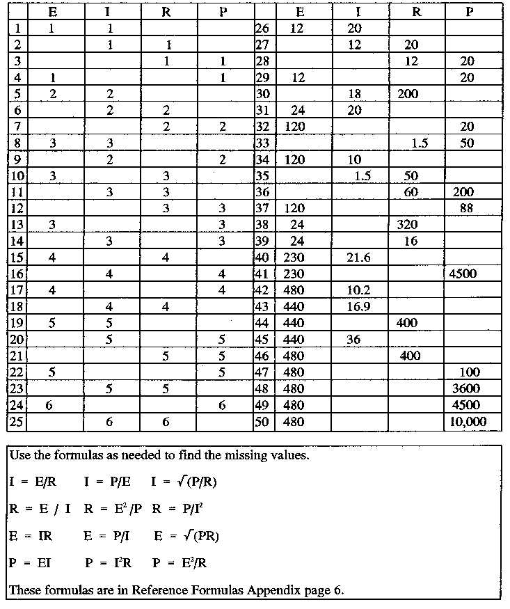
- Ohms Law Worksheet Answers
- Series and Parallel Circuits Worksheet Key
- Parallel Circuit Worksheet
- Electricity Circuit Worksheets 4th Grade
- Series Parallel Circuit Practice Problems
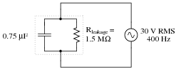
- AC Parallel Circuits
- Conversion Math Problems Worksheets
- Circuits Worksheet
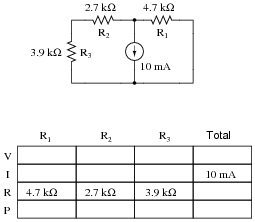
 Series Parallel Circuit Worksheet
 Series Parallel Circuit Worksheet Answers
 Electronic Circuits Series and Parallel
 Box Fill Calculation Worksheet
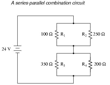
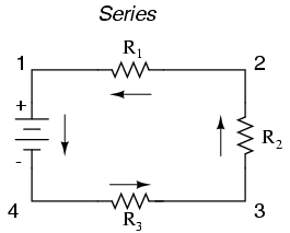
 Series Parallel Circuit
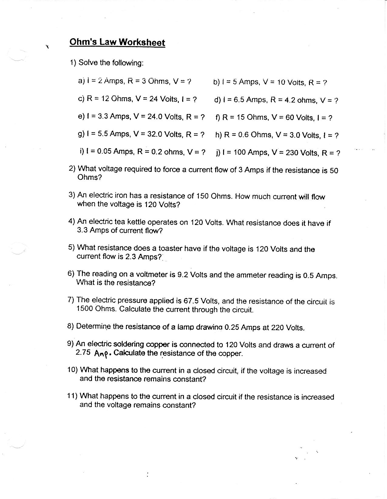
 Ohms Law Worksheet Answers
 Series and Parallel Circuits Worksheet Key
 Parallel Circuit Worksheet
 Electricity Circuit Worksheets 4th Grade

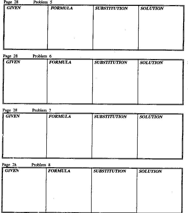
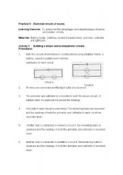
 Series Parallel Circuit Practice Problems
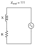
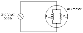
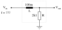
 AC Parallel Circuits
 Conversion Math Problems Worksheets
 Circuits Worksheet
More Other Worksheets
Kindergarten Worksheet My RoomSpanish Verb Worksheets
Cooking Vocabulary Worksheet
DNA Code Worksheet
Meiosis Worksheet Answer Key
Art Handouts and Worksheets
7 Elements of Art Worksheets
All Amendment Worksheet
Symmetry Art Worksheets
Daily Meal Planning Worksheet
What is the main difference between a series and a parallel circuit?
The main difference between a series and a parallel circuit is the way components are connected. In a series circuit, components are connected in a single path, so the same current flows through each component. In contrast, in a parallel circuit, components are connected on separate branches, allowing different currents to flow through each component independently. This means that if one component fails in a series circuit, the entire circuit will be affected, whereas in a parallel circuit, if one component fails, the other components can still function.
What happens to the total resistance in a series circuit as more resistors are added?
The total resistance in a series circuit increases as more resistors are added. This is because in a series circuit, current flows through each resistor one after the other, resulting in an accumulation of resistance that adds up with each additional resistor. Therefore, as more resistors are added in series, the total resistance in the circuit also increases.
How does the current flow in a series circuit?
In a series circuit, the current flows in a single pathway, with all components connected in a line so that the same current passes through each component. This means that the current is constant throughout the circuit and the flow of electrons is continuous from one end of the circuit to the other, without any branches or splits. If one component breaks or is removed, the circuit is broken and no current can flow.
How does the voltage differ across resistors in a series circuit?
In a series circuit, the voltage across each resistor is directly proportional to the resistance of that resistor. As such, the voltage across each resistor will differ depending on the value of the resistance. The total voltage in a series circuit is equal to the sum of the voltages across each resistor.
What happens to the total resistance in a parallel circuit as more resistors are added?
As more resistors are added to a parallel circuit, the total resistance decreases. This is because adding more paths for the current to flow creates additional routes through which the electricity can pass, reducing the overall resistance in the circuit.
How does the current flow in a parallel circuit?
In a parallel circuit, the current flows through each branch of the circuit independently. This means that the current is divided among the different branches based on their individual resistance. Each branch offers a different path for the current to flow, allowing devices to operate independently of each other and receive the current needed for proper functioning.
How does the voltage differ across resistors in a parallel circuit?
In a parallel circuit, the voltage across each resistor is the same. This is because the voltage is constant throughout all branches of a parallel circuit, allowing the voltage drop across each resistor to be identical.
How do you calculate the total resistance in a series circuit?
To calculate the total resistance in a series circuit, you simply need to add up the individual resistances of each component in the circuit. This is because in a series circuit, the current flows through each component consecutively, and the total resistance is the sum of all the resistances in the circuit. Mathematically, you can express this as Rt = R1 + R2 + R3 + ..., where Rt is the total resistance and R1, R2, R3, etc., are the resistances of each component.
How do you calculate the total resistance in a parallel circuit?
To calculate the total resistance in a parallel circuit, you need to use the formula: 1/Rtotal = 1/R1 + 1/R2 + 1/R3 + ... + 1/Rn, where Rtotal is the total resistance, and R1, R2, R3, etc. are the resistances of each individual branch in the circuit. This formula involves taking the reciprocal of each resistance value, summing up all the reciprocals, and then taking the reciprocal of the final sum to find the total resistance.
What are some examples of everyday devices that use series and parallel circuits?
Some examples of everyday devices that use series and parallel circuits include Christmas lights (series circuit), wall sockets in a home (parallel circuit), television remote controls (series circuit), and home light switches (parallel circuit).


Have something to share?
Who is Worksheeto?
At Worksheeto, we are committed to delivering an extensive and varied portfolio of superior quality worksheets, designed to address the educational demands of students, educators, and parents.


Comments