Circuit Diagram Worksheet
A circuit diagram worksheet is a helpful tool that allows students to visualize and understand the different components of an electrical circuit. By providing a clear and organized representation of the circuit's entity and subject, this worksheet can greatly assist students in grasping the concepts and principles related to electrical circuits. Whether you are a teacher looking for engaging educational materials or a student seeking additional practice, a carefully designed circuit diagram worksheet can be a valuable resource.
Table of Images 👆
- Electrical Circuit Symbol for Electromagnet
- Origami Fox Diagram
- Menstrual Cycle Diagram Worksheet
- Parallel Circuit Diagram Worksheet
- Electrical Circuit Symbols
- ATmega8 Pin Diagram
- Single Line Electrical Diagram Symbols
- Molecular Orbital Theory Diagram
- Power Antenna Wiring Diagram
- 1969 Ford F100 Wiring Diagram
- Electronic Symbols Clip Art
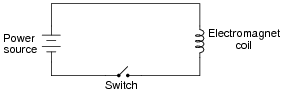
 Electrical Circuit Symbol for Electromagnet

 Origami Fox Diagram

 Menstrual Cycle Diagram Worksheet
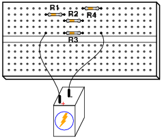
 Parallel Circuit Diagram Worksheet
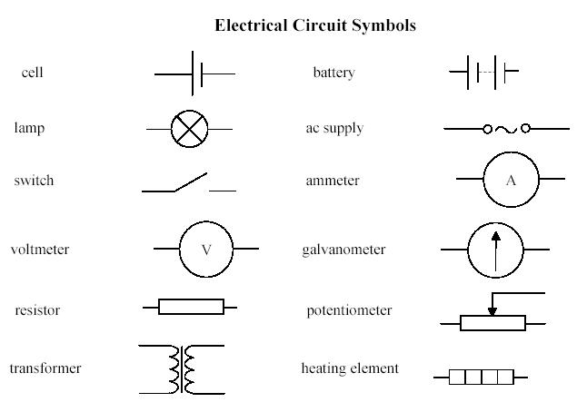
 Electrical Circuit Symbols
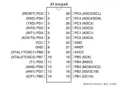
 ATmega8 Pin Diagram
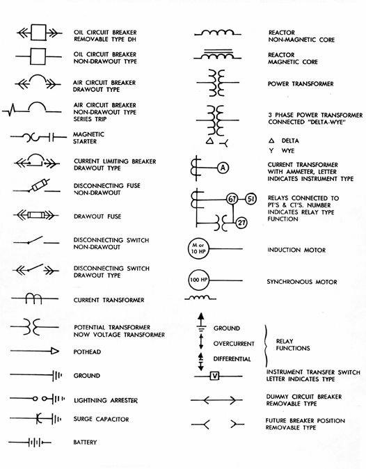
 Single Line Electrical Diagram Symbols
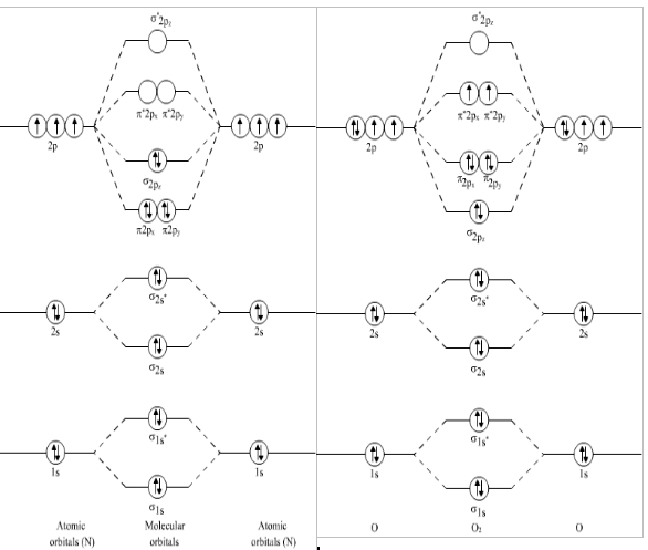
 Molecular Orbital Theory Diagram

 Power Antenna Wiring Diagram

 1969 Ford F100 Wiring Diagram

 Electronic Symbols Clip Art

 Electronic Symbols Clip Art
More Other Worksheets
Kindergarten Worksheet My RoomSpanish Verb Worksheets
Cooking Vocabulary Worksheet
DNA Code Worksheet
Meiosis Worksheet Answer Key
Art Handouts and Worksheets
7 Elements of Art Worksheets
All Amendment Worksheet
Symmetry Art Worksheets
Daily Meal Planning Worksheet
What is a circuit diagram?
A circuit diagram is a visual representation of an electrical circuit, showing how various components such as resistors, capacitors, transistors, and power sources are connected through wires to form a complete circuit. It uses standardized symbols to depict each component and the connections between them, providing a clear and concise way to understand the design and functioning of the circuit.
What are the basic components of a circuit diagram?
A circuit diagram typically consists of symbols representing components such as resistors, capacitors, transistors, and power sources, interconnected by lines that represent wires connecting these components. It also includes labels or values for each component, indicating their specific properties or values within the circuit. Additionally, there may be arrows or directions of current flow to indicate the direction in which electricity is flowing through the circuit.
How are wires represented in a circuit diagram?
In a circuit diagram, wires are typically represented as straight lines connecting the different components or elements of the circuit. The lines indicate the flow of electric current between the components and show how they are interconnected within the circuit design.
What is the purpose of a resistor in a circuit diagram?
The purpose of a resistor in a circuit diagram is to limit the flow of current in a circuit, control the voltage levels, and protect components from damage by ensuring the correct amount of current passes through them. Resistors are used to regulate the amount of current that flows through different parts of a circuit and are essential for proper functioning and safety of electronic devices.
What does a battery symbol represent in a circuit diagram?
The battery symbol in a circuit diagram represents a power source or a voltage source whose purpose is to provide electrical energy for the circuit to function. It typically has a longer line representing the positive terminal and a shorter line representing the negative terminal.
What is the function of a switch in a circuit diagram?
The function of a switch in a circuit diagram is to control the flow of electrical current in a circuit by either allowing or interrupting the flow of electricity. When the switch is closed (turned on), it completes the circuit and allows current to flow through it, enabling the devices or components in the circuit to operate. When the switch is open (turned off), it breaks the circuit, stopping the flow of current and turning off the devices or components connected to it.
How is an LED (light-emitting diode) represented in a circuit diagram?
An LED is represented in a circuit diagram by a symbol that looks like an arrow pointing away from a line, indicating the direction of light emission. It also has two longer lines representing the two terminals of the LED, with the longer line on the right side symbolizing the positive terminal (anode) and the shorter line on the left side representing the negative terminal (cathode).
What is the purpose of a capacitor in a circuit diagram?
A capacitor in a circuit diagram is used to store and release electrical energy. It can store energy in the form of an electric field when it is connected to a voltage source, and then release this energy when the voltage source is removed or the capacitor is connected to another part of the circuit. Capacitors are commonly used in circuits for filtering, timing, smoothing out voltage spikes, and energy storage applications.
How are complex circuits represented in a circuit diagram?
Complex circuits are represented in a circuit diagram by using various standard symbols to represent different components such as resistors, capacitors, transistors, and other electronic devices. These symbols are connected by lines to show the flow of electric current and the connections between components. Additionally, the circuit diagram may include labels and annotations to provide further information about the circuit's functionality and components.
What are the benefits of using circuit diagrams in electrical engineering?
Circuit diagrams are essential in electrical engineering as they provide a visual representation of electrical components and their connections within a circuit. This visual aid helps engineers to understand, analyze, and design complex circuits more effectively. It also allows for easier troubleshooting and debugging of electrical systems, as issues can be easily identified and isolated within the diagram. Additionally, circuit diagrams enable efficient communication and collaboration among engineers, making it easier to convey design ideas and modifications accurately. Overall, using circuit diagrams in electrical engineering enhances efficiency, accuracy, and clarity in circuit design and analysis processes.


Have something to share?
Who is Worksheeto?
At Worksheeto, we are committed to delivering an extensive and varied portfolio of superior quality worksheets, designed to address the educational demands of students, educators, and parents.


Comments