Series Circuit Worksheet
Are you a student or an educator looking for a helpful resource to reinforce your understanding of series circuits? Look no further! This worksheet is designed to provide you with the opportunity to practice and solidify your knowledge of series circuits, a fundamental concept in electrical engineering and physics.
Table of Images 👆
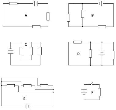
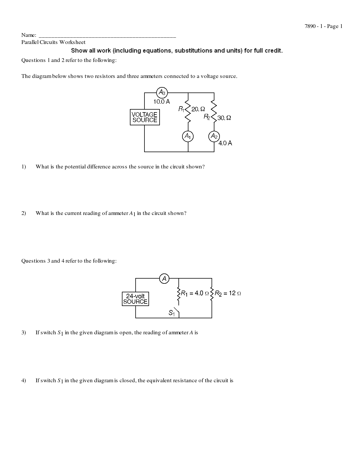
- Parallel Circuit Diagram Worksheet
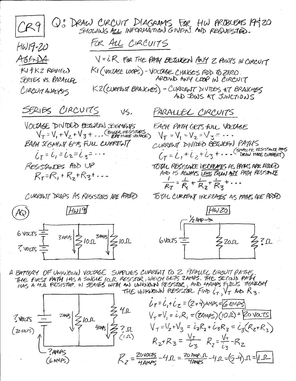
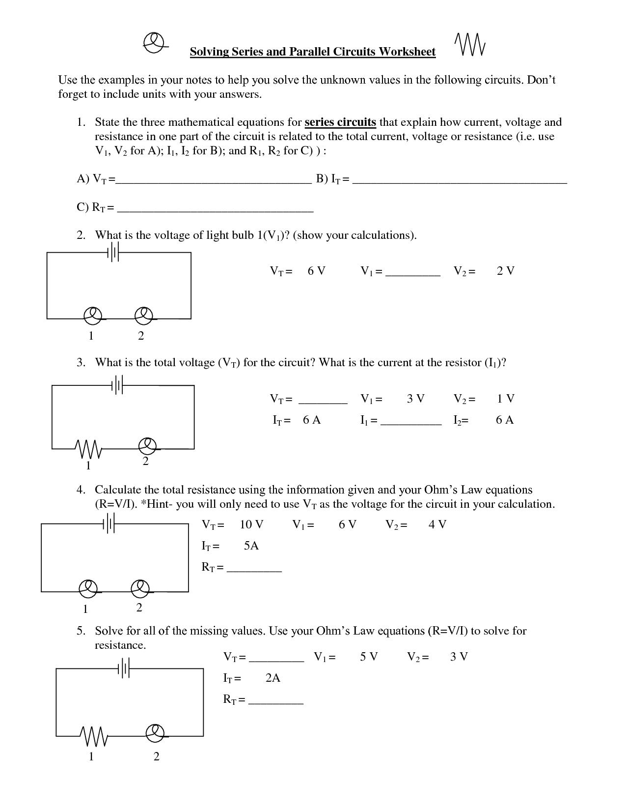
- Series vs Parallel Circuits Worksheet
- Series and Parallel Circuit Worksheet Answers
- Series Parallel Circuit Worksheet Answers
- Series Parallel Circuit Worksheet
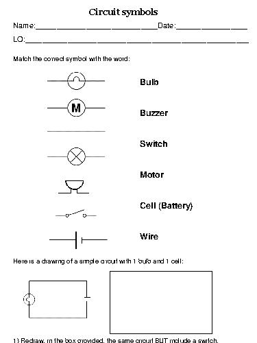
- Circuit Symbols Worksheet
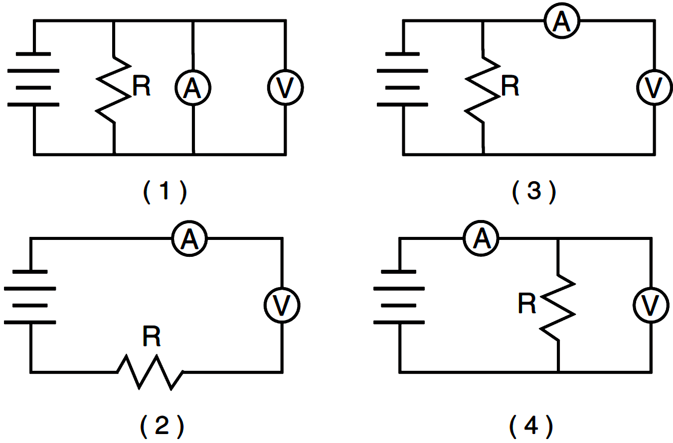
- Resistor Circuit Diagram with Ammeter and Voltmeter
- Series Parallel Circuit Worksheet with Answers
- Bill Nye Static Electricity Worksheet Answers
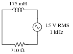
- Simple Power Supply Circuit Diagram
More Other Worksheets
Kindergarten Worksheet My RoomSpanish Verb Worksheets
Cooking Vocabulary Worksheet
DNA Code Worksheet
Meiosis Worksheet Answer Key
Art Handouts and Worksheets
7 Elements of Art Worksheets
All Amendment Worksheet
Symmetry Art Worksheets
Daily Meal Planning Worksheet
What is a series circuit?
A series circuit is a type of electrical circuit in which the components are connected in a single pathway so that the same current flows through each component in the circuit. This means that if one component fails or is removed, the entire circuit will be broken and none of the components will function. The voltage in a series circuit is divided among the components, with the total voltage being equal to the sum of the individual voltage drops across each component.
How does current flow in a series circuit?
In a series circuit, current flows through a single pathway, passing sequentially through each component connected in the circuit. The current is the same at any point in the circuit because there are no alternate paths for it to take. As it flows through each component, it encounters resistance, which affects the overall flow of current in the circuit. If one component fails or is removed, the circuit becomes open and no current can flow through it.
What happens to the current at each component in a series circuit?
In a series circuit, the current remains the same at each component. This is because there is only one path for the current to flow through, so the current is constant throughout the circuit. As a result, the total current supplied by the power source is equal to the sum of the currents flowing through each component.
What is the relationship between the voltage across each component in a series circuit?
In a series circuit, the voltage across each component is divided based on the resistance of each component. The total voltage of the circuit is equal to the sum of the voltages across each component. The voltage across each component is directly proportional to its resistance, meaning that the component with the higher resistance will have a higher voltage drop across it compared to a component with lower resistance.
How can you calculate the total resistance in a series circuit?
To calculate the total resistance in a series circuit, you simply add up all the individual resistances in the circuit. This means that the total resistance (Rt) is equal to the sum of all the resistors (R1 + R2 + R3 + ...). This concept arises from the fact that current has no choice but to flow through each resistor in sequence, leading to a cumulative effect on resistance. By adding up the resistances, you can determine the overall resistance in the series circuit.
How is the total current calculated in a series circuit?
In a series circuit, the total current is calculated by summing the individual currents flowing through each component connected in the circuit. This means that the total current flowing through the circuit is the same at every point in the series, as there is only one path for the current to flow. Ohm's Law, I = V/R, can be used to calculate the total current by dividing the total voltage of the circuit by the total resistance.
What happens to the brightness or intensity of light bulbs connected in a series circuit?
In a series circuit, the brightness or intensity of light bulbs decreases as more bulbs are added to the circuit. This is because the total voltage in a series circuit is divided among all the bulbs, resulting in each bulb receiving less voltage and therefore emitting less light.
What happens to the total resistance as more resistors are added in a series circuit?
The total resistance increases as more resistors are added in a series circuit. This is because the total resistance in a series circuit is the sum of the individual resistances of each resistor. As more resistors are added, the total resistance in the circuit increases proportionally to the sum of the resistances of all the resistors in series.
What happens to the total voltage in a series circuit compared to the individual voltages across each component?
In a series circuit, the total voltage across all components is equal to the sum of the individual voltages across each component. Therefore, the total voltage in a series circuit is the same as the sum of the individual voltages across each component.
How does a break or open circuit affect a series circuit?
In a series circuit, a break or open circuit will interrupt the flow of current, causing the entire circuit to stop functioning. Since components in a series circuit are connected one after the other along a single path, any interruption will prevent the current from flowing through all components downstream of the break. As a result, none of the components in the circuit will receive current and no work will be done by the circuit.
Have something to share?
Who is Worksheeto?
At Worksheeto, we are committed to delivering an extensive and varied portfolio of superior quality worksheets, designed to address the educational demands of students, educators, and parents.







Comments