Simple Series Circuits Worksheet
Are you a student or an electronics enthusiast who is looking for a helpful resource to practice and test your understanding of simple series circuits? Look no further! Our Simple Series Circuits Worksheet is designed just for you. This worksheet focuses on the important concepts and principles related to series circuits and will provide you with ample opportunities to apply your knowledge and practice solving various problems related to this topic.
Table of Images 👆
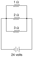
 Parallel Circuit Diagram Worksheet
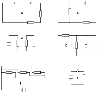
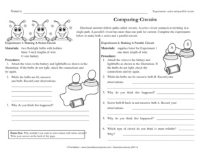
 Series and Parallel Circuits Worksheets
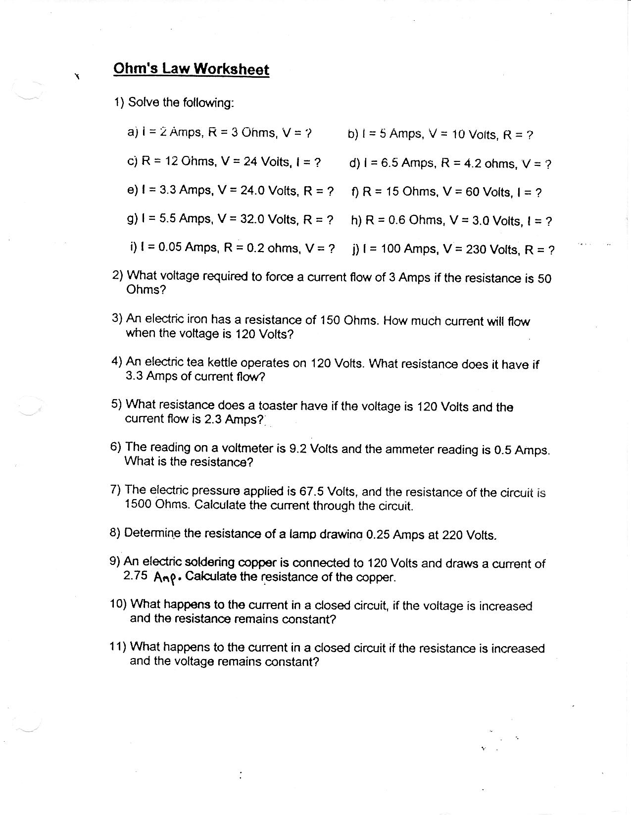
 Ohms Law Worksheet Answers
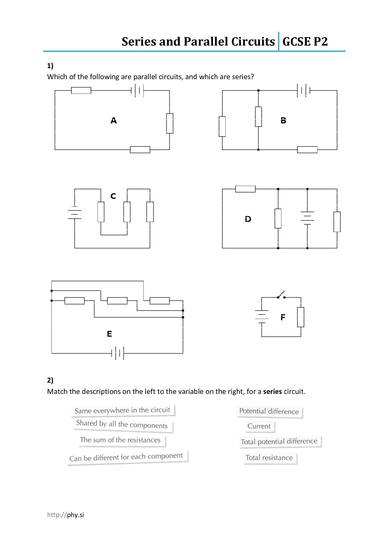
 Series and Parallel Circuits Worksheets
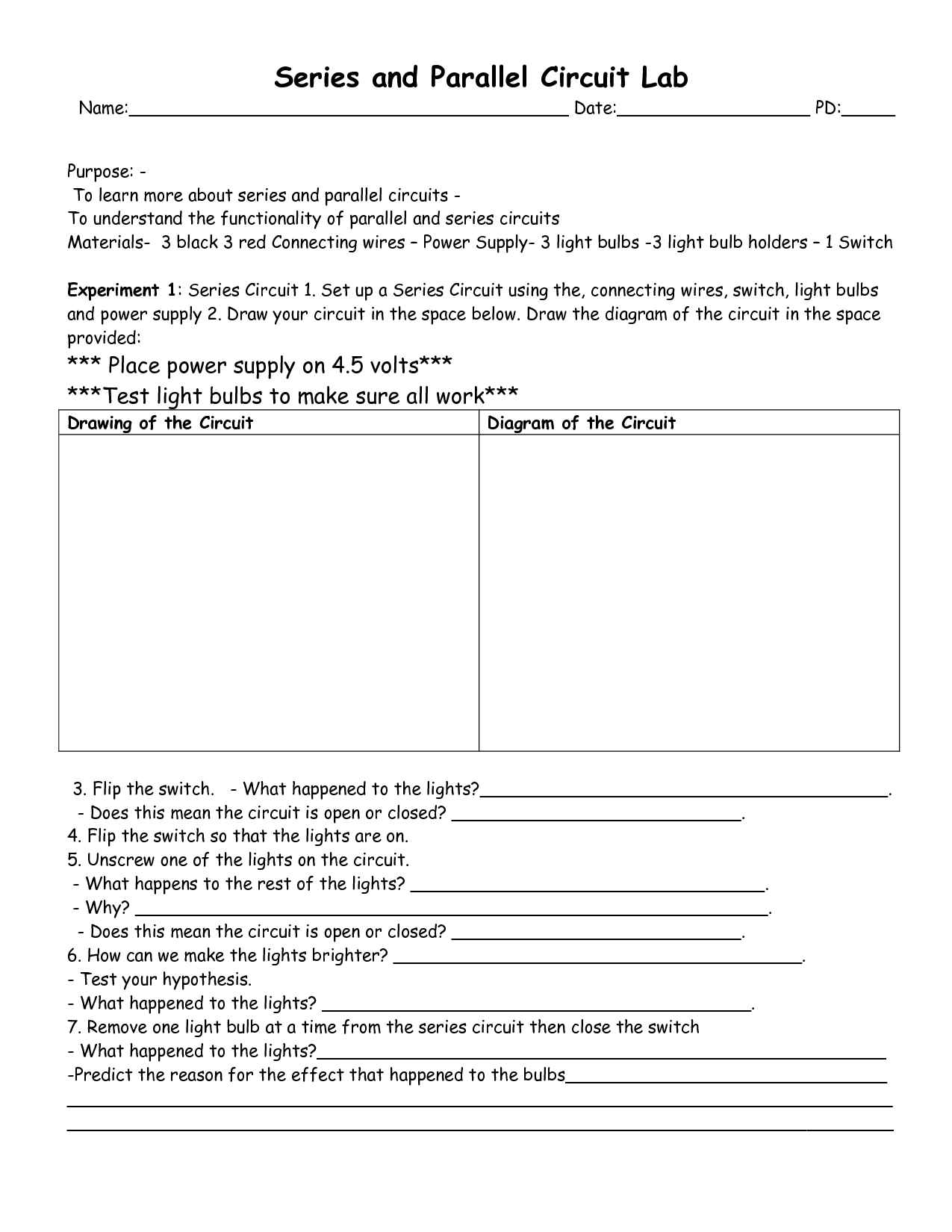
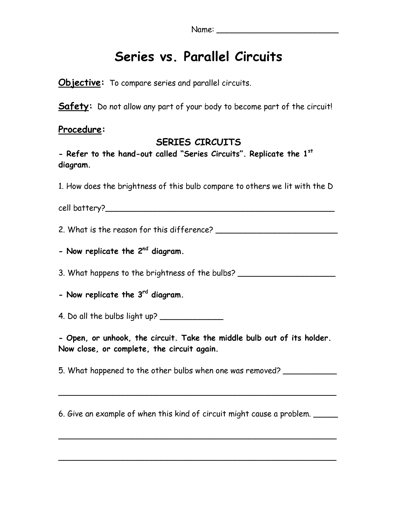
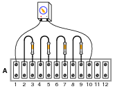
 Series and Parallel Circuit Lab
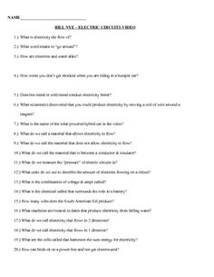
 Bill Nye Electric Circuit Worksheet
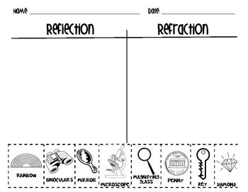
 Light Reflection and Refraction Worksheet
 Series and Parallel Circuits Worksheets
 Worksheets Science Circuit
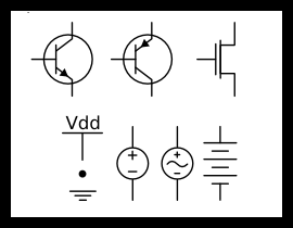
 Circuit Diagram Symbols
 Combining Like Terms

 Grounding Kit Diagram

 Grounding Kit Diagram
 Grounding Kit Diagram

 Grounding Kit Diagram

 Grounding Kit Diagram

 Grounding Kit Diagram
More Other Worksheets
Kindergarten Worksheet My RoomSpanish Verb Worksheets
Cooking Vocabulary Worksheet
DNA Code Worksheet
Meiosis Worksheet Answer Key
Art Handouts and Worksheets
7 Elements of Art Worksheets
All Amendment Worksheet
Symmetry Art Worksheets
Daily Meal Planning Worksheet
What is a series circuit?
A series circuit is a type of electric circuit in which the current flows through a single path, connecting the components in a straight line one after the other. In a series circuit, the same current flows through each component, and the total voltage is divided among the components. If one component in a series circuit breaks or becomes disconnected, the entire circuit will be interrupted and no current will flow.
What are the components of a series circuit?
A series circuit consists of components connected in a single loop, where the current flows in one continuous path. The components in a series circuit are connected end to end, meaning that the same current passes through each component in the circuit. Components in a series circuit include a power source (such as a battery or generator), wires for connecting the components, and one or more resistors, light bulbs, or other devices that create a load in the circuit.
How do the voltage and current behave in a series circuit?
In a series circuit, the voltage across each component adds up to the total voltage supplied by the source, and the current flowing through each component is the same throughout the circuit. This means that the voltage and current behave consistently in a series circuit, with the total resistance determining the overall current flowing through the circuit based on Ohm's Law (V=IR).
What is the total resistance in a series circuit?
The total resistance in a series circuit is the sum of all individual resistances in the circuit. Each resistor in a series circuit adds to the total resistance, making the total resistance equal to the sum of all resistors in the circuit.
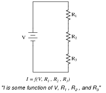
How do you calculate the total resistance in a series circuit?
To calculate the total resistance in a series circuit, you simply add up the resistances of each individual component in the circuit. In a series circuit, the total resistance is equal to the sum of all the resistances present in the circuit. This can be expressed as: total resistance = R1 + R2 + R3 + ... + Rn, where R1, R2, R3, and Rn represent the individual resistances of each component in the circuit.
How does adding resistors in a series circuit affect the total resistance?
In a series circuit, adding resistors increases the total resistance. This is because the total resistance in a series circuit is the sum of all individual resistances. Therefore, as you add more resistors in series, the total resistance increases.
How does adding resistors in a series circuit affect the total current?
Adding resistors in series in a circuit will increase the total resistance, which in turn decreases the total current flowing through the circuit according to Ohm's Law (I = V/R). This is because as resistance increases, the voltage across the circuit remains constant (assuming a fixed voltage source), leading to a decrease in current flow.
How does adding resistors in a series circuit affect the voltage across each resistor?
In a series circuit, adding resistors will increase the total resistance in the circuit, which in turn will decrease the total current flowing through the circuit due to Ohm's Law (V=IR). This decrease in current results in a decrease in the voltage drop across each resistor as the total voltage in the circuit remains constant (Kirchhoff's Voltage Law). Therefore, adding resistors in a series circuit will cause the voltage across each resistor to decrease as the total resistance increases.
How does the brightness of bulbs connected in a series circuit change when more bulbs are added?
In a series circuit, the brightness of bulbs connected in the circuit decreases as more bulbs are added. This is because the total resistance in the circuit increases with each additional bulb, causing less current to flow through each bulb, resulting in reduced brightness.
How does the total current change when bulbs of different resistance are connected in a series circuit?
In a series circuit, the total current decreases when bulbs of different resistance are connected because the current encounters more resistance as it passes through each bulb. This results in a reduction of the overall flow of current in the circuit as compared to if the bulbs were of equal resistance.


Have something to share?
Who is Worksheeto?
At Worksheeto, we are committed to delivering an extensive and varied portfolio of superior quality worksheets, designed to address the educational demands of students, educators, and parents.


Comments