Simple Electric Circuit Worksheet
Are you an educator or a parent searching for a useful teaching tool to help students understand the concepts of electric circuits? Look no further, as this simple electric circuit worksheet is designed to engage and educate young learners on the basics of electricity. This worksheet is especially created for elementary or middle school students who are learning about circuits for the first time.
Table of Images 👆

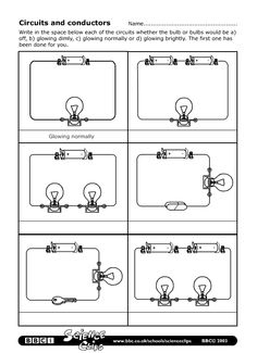
 Electrical Circuit Examples
 Electrical Circuit Diagram Worksheet

 Circuit Diagram Worksheet 5th Grade
 Conductors and Insulators Worksheet 4th
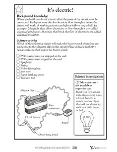
 Electricity Circuit Worksheets 4th Grade

 FMEA Failure Mode Examples
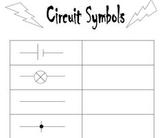
 Circuit Symbols Worksheet
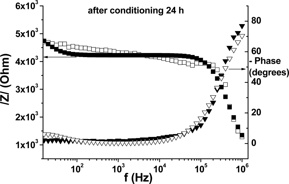
 Bode Plot

 Electricity Crossword Puzzle Answers

 Electricity Crossword Puzzle Answers

 Electricity Crossword Puzzle Answers

 Electricity Crossword Puzzle Answers

 Electricity Crossword Puzzle Answers

 Electricity Crossword Puzzle Answers

 Electricity Crossword Puzzle Answers

 Electricity Crossword Puzzle Answers

 Electricity Crossword Puzzle Answers
More Other Worksheets
Kindergarten Worksheet My RoomSpanish Verb Worksheets
Cooking Vocabulary Worksheet
DNA Code Worksheet
Meiosis Worksheet Answer Key
Art Handouts and Worksheets
7 Elements of Art Worksheets
All Amendment Worksheet
Symmetry Art Worksheets
Daily Meal Planning Worksheet
What is an electric circuit?
An electric circuit is a closed loop through which an electric current can flow. It is comprised of electrical components such as wires, resistors, capacitors, inductors, and various other elements that are connected in a specific way to perform a desired function, such as powering a light bulb or electronic device. The flow of electrons within the circuit is facilitated by a voltage source, such as a battery or power supply, that provides the necessary energy for the electrons to move through the circuit and perform work.
What are the main components of a simple electric circuit?
The main components of a simple electric circuit are a power source (such as a battery), conductive materials (such as wires), a load (such as a light bulb), and a switch (to control the flow of electricity). The power source provides electrical energy, which flows through the conductive materials to power the load. The switch allows you to control when the circuit is open or closed, thus controlling the flow of electricity to the load.
How does a switch affect an electric circuit?
A switch in an electric circuit functions to either complete or break the flow of electricity, allowing control over whether the circuit is connected or disconnected. When the switch is in the "on" position, it closes the circuit, allowing current to flow and activating the components connected to it. Conversely, in the "off" position, the switch breaks the circuit, stopping the flow of electricity and deactivating the components. This ability to control the flow of electricity enables switches to turn devices on or off, providing a simple and effective way to manage electric circuits.
What is the purpose of a resistor in a circuit?
The purpose of a resistor in a circuit is to limit or control the amount of current that flows through the circuit. Resistors are used to regulate voltage levels, protect components from excessive current, and divide voltages within a circuit. They also are used to adjust signal levels, set bias currents, and create voltage drops, among other functions in electronic circuits.
How does an electric current flow in a circuit?
An electric current flows in a circuit when an external voltage source, such as a battery, creates a potential difference that pushes charged particles, usually electrons, along a conductive path. The electrons move from the negative terminal of the source, through the conductive material, and back to the positive terminal, completing the circuit. This flow of electrons constitutes an electric current, which carries energy and can power devices connected within the circuit.
How do voltage and current relate to each other in a circuit?
Voltage and current are related in a circuit through Ohm's Law, which states that the current flowing through a conductor is directly proportional to the voltage applied across it, and inversely proportional to the resistance of the conductor. This means that an increase in voltage will result in a corresponding increase in current flow, as long as the resistance remains constant. Conversely, a decrease in voltage will lead to a decrease in current flow.
What is the role of a battery in an electric circuit?
The role of a battery in an electric circuit is to provide a source of electrical energy by converting chemical energy into electrical energy. The battery creates a potential difference, or voltage, which drives the flow of electrons through the circuit, providing power to operate devices such as lights, motor, or electronic gadgets. It acts as a portable and self-contained power source that can be connected to the circuit to allow for the flow of current and the transfer of energy.
How do you calculate the total resistance of a series circuit?
To calculate the total resistance of a series circuit, you simply add up the resistance values of each component in the circuit. This can be done by adding the resistance values together: R_total = R1 + R2 + R3 + ... + Rn, where R1, R2, R3, and so on are the resistance values of each individual component in the series circuit.
How do you calculate the total current of a parallel circuit?
To calculate the total current of a parallel circuit, you simply add up the currents of each individual branch in the circuit. This is because in a parallel circuit, the total current is equal to the sum of the currents flowing through each branch. So, you can calculate the total current by adding up the currents using the formula: Total current = I1 + I2 + I3 + ... + In, where I1, I2, I3, etc. are the currents flowing through each branch of the parallel circuit.
How does the brightness of a lightbulb in a circuit change when the voltage is increased?
When the voltage is increased in a circuit with a lightbulb, the brightness of the lightbulb also increases. This is because the voltage directly affects the flow of current through the filament of the lightbulb, causing it to produce more intense light as more energy is being supplied to it. Additionally, the higher voltage results in more power being delivered to the lightbulb, leading to a brighter illumination.


Have something to share?
Who is Worksheeto?
At Worksheeto, we are committed to delivering an extensive and varied portfolio of superior quality worksheets, designed to address the educational demands of students, educators, and parents.


Comments