Simple Circuit Worksheet
A simple circuit worksheet is a valuable tool for teaching and reinforcing the concepts of electrical circuits to students. Whether you are an educator seeking to engage learners in hands-on activities or a parent looking to supplement your child's science education at home, a simple circuit worksheet provides an effective way to introduce the key elements of a circuit and explore their functions. By systematically breaking down the components, such as batteries, wires, switches, and light bulbs, this worksheet is designed to help students understand the relationships between entities in a circuit and the role each subject plays in the flow of electricity.
Table of Images 👆
- Series and Parallel Circuits Worksheets
- Ohms Law Worksheet Answers
- Basic Series and Parallel Circuits
- 555 DC Motor Control Circuit
- Molar Mass Worksheet Answers
- Series and Parallel Circuit Worksheet Answers
- Curve Tracer Circuit Oscilloscope
- Light-Emitting Diodes LEDs
- Electrical Transformer Diagram
- John Quincy Adams Drawing
- Grounding Safety Spreadsheet
- Buzzer Symbol
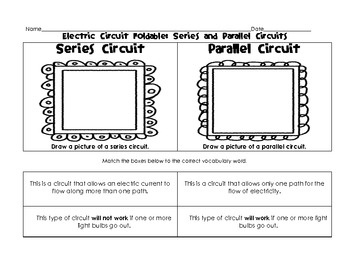
 Series and Parallel Circuits Worksheets
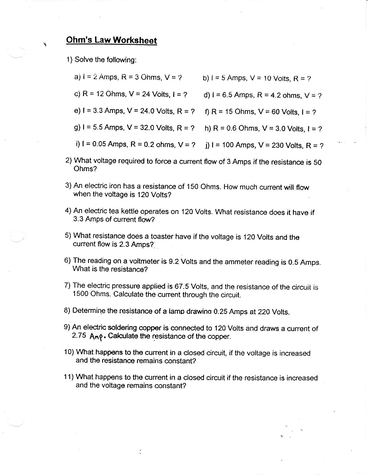
 Ohms Law Worksheet Answers
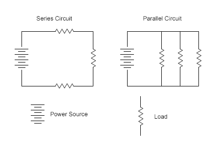
 Basic Series and Parallel Circuits
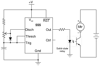
 555 DC Motor Control Circuit
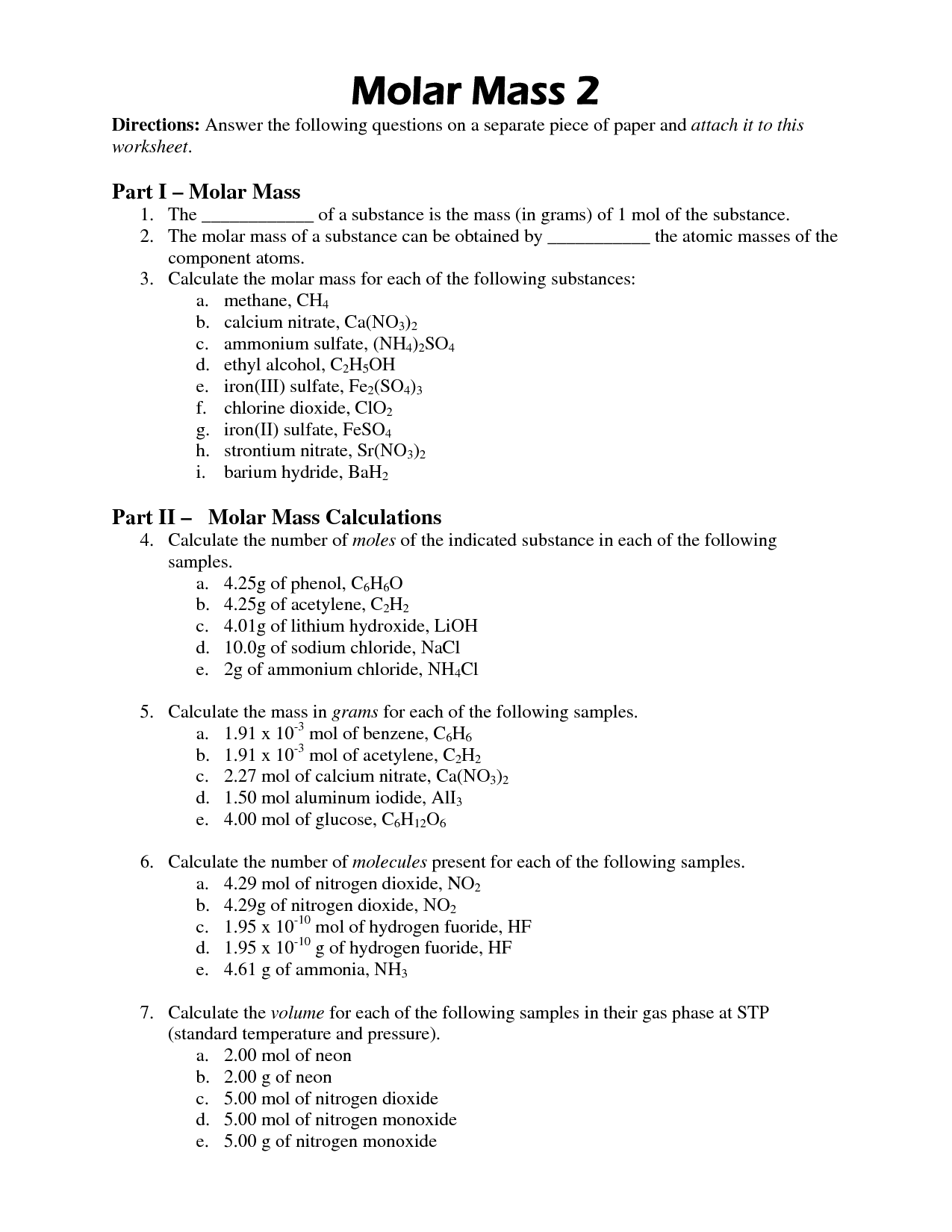
 Molar Mass Worksheet Answers

 Series and Parallel Circuit Worksheet Answers
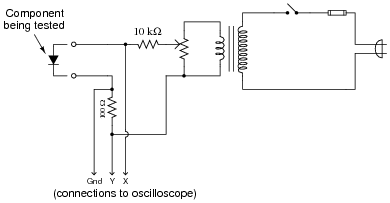
 Curve Tracer Circuit Oscilloscope
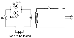
 Light-Emitting Diodes LEDs
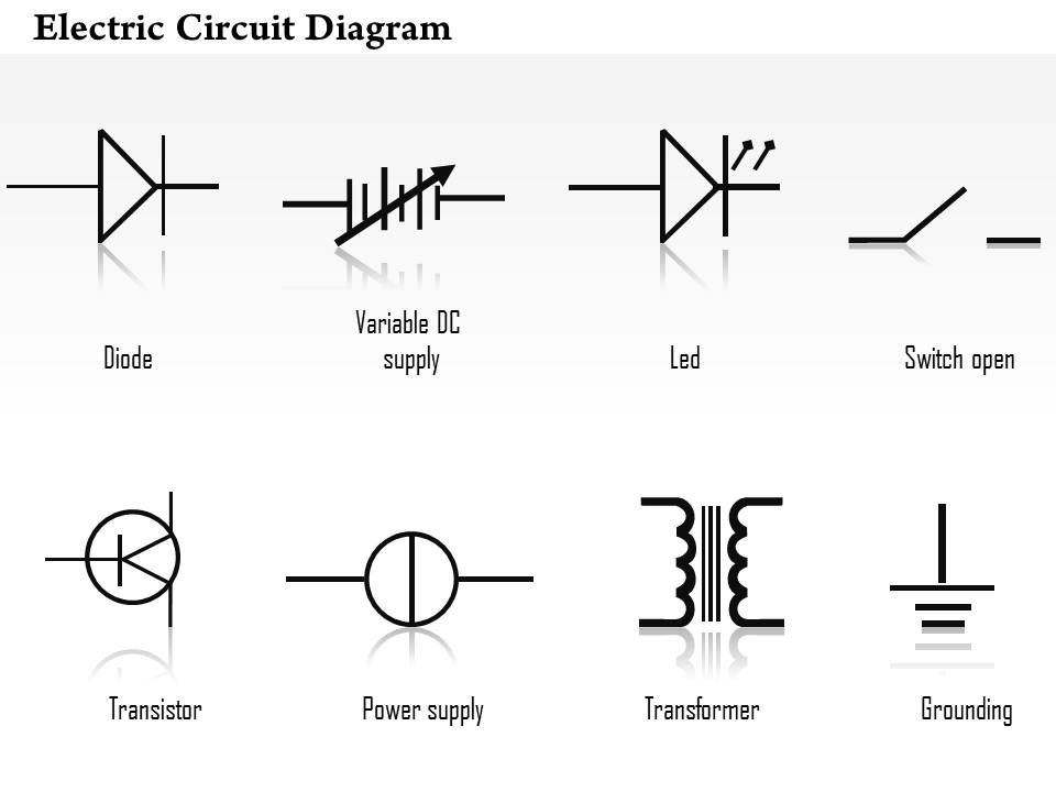
 Electrical Transformer Diagram
 John Quincy Adams Drawing
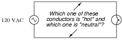
 Grounding Safety Spreadsheet

 Buzzer Symbol

 Buzzer Symbol

 Buzzer Symbol

 Buzzer Symbol
More Other Worksheets
Kindergarten Worksheet My RoomSpanish Verb Worksheets
Cooking Vocabulary Worksheet
DNA Code Worksheet
Meiosis Worksheet Answer Key
Art Handouts and Worksheets
7 Elements of Art Worksheets
All Amendment Worksheet
Symmetry Art Worksheets
Daily Meal Planning Worksheet
What is a simple circuit?
A simple circuit is a basic electrical circuit that consists of a power source, a load (such as a light bulb or motor), and a pathway for electric current to flow, typically a wire. This type of circuit allows electricity to move through it in a continuous loop to power the load, demonstrating the fundamental principles of electrical circuits.
What are the components of a simple circuit?
A simple circuit consists of a power source (such as a battery), conductive wires to carry the electric current, a load (such as a light bulb or motor) that uses the electrical energy, and a switch to control the flow of electricity. Additionally, some circuits may include resistors to regulate the flow of current or capacitors to store electrical charge.
What is the purpose of a battery in a circuit?
The purpose of a battery in a circuit is to provide a source of electrical energy to power the components within the circuit. It acts as a voltage source, creating a potential difference that allows charge to flow through the circuit, enabling the electrical devices to function and perform their intended tasks.
How does a switch affect the flow of electricity in a circuit?
A switch controls the flow of electricity in a circuit by opening or closing the circuit. When the switch is closed, it allows electricity to flow through the circuit, completing the path for the electrical current. Conversely, when the switch is open, it interrupts the flow of electricity, preventing the current from circulating through the circuit. In summary, a switch has the ability to either enable or disable the flow of electricity in a circuit, providing a way to control the operation of electrical devices.
What is the role of a resistor in a circuit?
A resistor in a circuit acts to impede the flow of electrical current, thereby controlling the amount of current that passes through a specific part of the circuit. This helps to regulate voltage levels, limit current, and protect other components from damage due to excessive current flow. Resistors are also used for voltage division, signal conditioning, and reducing current flow to desired levels in various electronic devices and circuits.
How does a light bulb work in a circuit?
A light bulb works in a circuit by utilizing the flow of electric current to generate light. When the circuit is closed and voltage is applied, electrons flow through the filament of the light bulb, which resists the flow and generates heat. As the filament heats up, it emits light through a process called incandescence, providing illumination in the surrounding area.
What is the purpose of wires in a circuit?
The purpose of wires in a circuit is to provide a path for the flow of electric current between various components like batteries, switches, resistors, and light bulbs. Wires are used to connect these components and form a complete circuit, allowing electricity to flow and power the devices or perform specific functions within the circuit.
What happens if a wire is disconnected or broken in a circuit?
If a wire is disconnected or broken in a circuit, it creates an open circuit which prevents the flow of electricity. This interruption in the circuit will cause the electrical devices or components downstream from the break to stop functioning or lose power. In simpler terms, the current cannot complete its path and no electrical energy will be able to flow through the circuit.
How does the current flow in a circuit?
Current flows in a circuit when there is a closed loop that allows for the movement of electric charges. When a voltage source, such as a battery, is connected to a circuit, it creates an electric field that pushes charged particles (usually electrons) through the circuit. These charged particles move from the negative terminal of the voltage source to the positive terminal, creating the flow of current in the circuit. The current flow is driven by the potential difference (voltage) between the two points in the circuit.
What is the difference between a series circuit and a parallel circuit?
In a series circuit, the components are connected in a single path, meaning that the same current flows through each component sequentially. Conversely, in a parallel circuit, the components are connected across multiple paths, allowing the current to split and flow through each component independently. Additionally, in a series circuit, if one component fails, it breaks the circuit, causing all components to stop working. In a parallel circuit, if one component fails, only that specific component is affected, while the others continue to operate.


Have something to share?
Who is Worksheeto?
At Worksheeto, we are committed to delivering an extensive and varied portfolio of superior quality worksheets, designed to address the educational demands of students, educators, and parents.


Comments