Lens Diagram Worksheet
A lens diagram worksheet is a helpful tool for anyone who wants to understand the principles behind the functioning of lenses. Whether you are a student studying optics, a photographer looking to improve your knowledge of lenses, or simply curious about how light bends and refracts through different mediums, this worksheet is designed to provide a clear and comprehensive overview of the subject.
Table of Images 👆
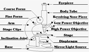
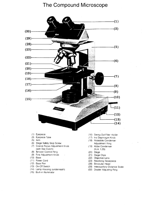
 Microscope with Labeled Parts
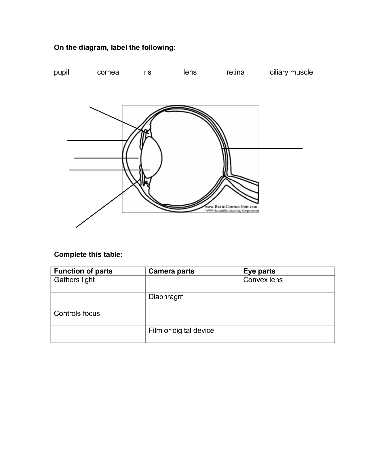
 Label Eye Parts Worksheet
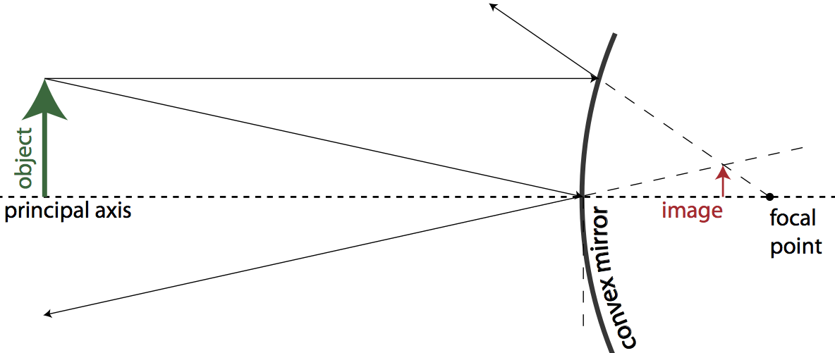
 Convex Mirror Worksheet

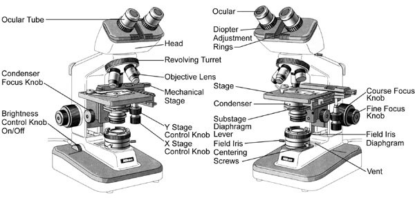
 Microscope Parts and Their Functions
 Compound Microscope Parts And Functions Quiz
 Compound Light Microscope Parts and Functions
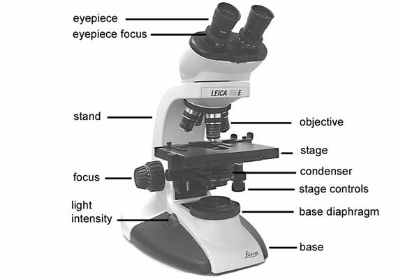
 Labels On Microscope
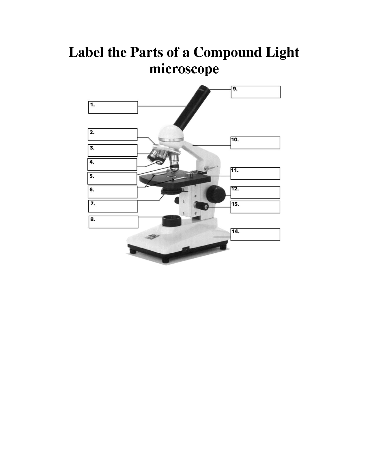
 Compound Light Microscope Parts Worksheet
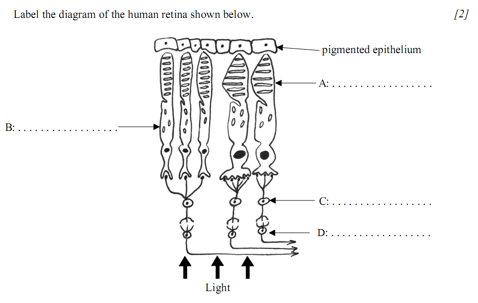
 Rod and Cone Cell Diagram
More Other Worksheets
Kindergarten Worksheet My RoomSpanish Verb Worksheets
Cooking Vocabulary Worksheet
DNA Code Worksheet
Meiosis Worksheet Answer Key
Art Handouts and Worksheets
7 Elements of Art Worksheets
All Amendment Worksheet
Symmetry Art Worksheets
Daily Meal Planning Worksheet
What is a lens diagram?
A lens diagram is a graphical representation that illustrates the key properties and characteristics of a lens, such as its focal length, principal axis, focal points, and the object and image distances in relation to the lens. This diagram is commonly used in physics and optics to help visualize and understand how light rays interact with lenses to form images.
What are the main elements or parts of a lens diagram?
The main elements of a lens diagram include the optical axis, which is the imaginary line passing through the center of the lens and perpendicular to its surface; the focal point, which is the point at which light rays either converge (for a concave lens) or diverge (for a convex lens); the focal length, which is the distance between the focal point and the lens; the object distance, which is the distance between the object and the lens; and the image distance, which is the distance between the image and the lens. These elements are essential for understanding how a lens forms images.
How is the focal length of a lens represented in a lens diagram?
The focal length of a lens is represented in a lens diagram by a vertical line or arrow drawn perpendicular to the optical axis, passing through the center of the lens. The distance between the focal point and the center of the lens is equal to the focal length of the lens. This helps to visually illustrate where light rays converge or diverge when passing through the lens.
What is the purpose of the principal axis in a lens diagram?
The principal axis in a lens diagram is a line passing through the center of the lens perpendicular to both surfaces. Its purpose is to provide a reference line for measuring distances within the lens, determining the focal point, and identifying the optical center of the lens. By using the principal axis, we can accurately analyze and describe the behavior of light rays passing through the lens.
What does the term "principal focus" refer to in a lens diagram?
The term "principal focus" in a lens diagram refers to a specific point on the principal axis of a lens where all incident light rays that are parallel to the axis converge to or diverge from after passing through the lens. This point helps determine the focal length of the lens and is important in understanding how the lens forms an image.
How are object and image distances represented in a lens diagram?
In a lens diagram, object distance is represented as the distance between the object and the lens, usually denoted as "u," while image distance is represented as the distance between the image and the lens, typically denoted as "v." These distances are measured along the principal axis of the lens, with object distance being measured from the object to the lens, and image distance being measured from the image to the lens.
What do converging lenses do in terms of light refraction?
Converging lenses refract light by bending the light rays that pass through them so that they converge or come together at a single point called the focal point. This refraction causes the light rays to change direction and focus, resulting in the formation of an image. Converging lenses are able to create real and inverted images, often used in applications such as cameras, magnifying glasses, and telescopes.
How are rays of light depicted in a lens diagram?
Rays of light are typically depicted in a lens diagram by drawing parallel rays entering the lens and either converging or diverging based on the lens type. These rays help show how the lens refracts light to form an image, with converging rays coming together at a point (for a converging lens) or diverging rays appearing to come from a point behind the lens (for a diverging lens).
What is the relationship between object distance and image distance in a lens diagram?
In a lens diagram, the relationship between object distance and image distance is governed by the lens equation (1/f = 1/dO + 1/dI), where f is the focal length of the lens, dO is the object distance, and dI is the image distance. Essentially, as the object distance changes, the image distance will also change in order to maintain the properties of the lens system. This relationship is crucial in understanding how images are formed by lenses and how they can be manipulated for various optical applications.
How is the size of the image compared to the size of the object in a lens diagram?
In a lens diagram, the size of the image is typically compared to the size of the object using the magnification ratio. The magnification ratio is the ratio of the size of the image to the size of the object. Depending on whether the image is magnified (larger than the object), reduced (smaller than the object), or the same size as the object, the magnification ratio will be greater than 1, less than 1, or equal to 1, respectively. This ratio helps to determine the relationship between the size of the image and the size of the object in the context of a lens diagram.


Have something to share?
Who is Worksheeto?
At Worksheeto, we are committed to delivering an extensive and varied portfolio of superior quality worksheets, designed to address the educational demands of students, educators, and parents.


Comments