Electrical Diagrams Worksheet
An electrical diagrams worksheet serves as a valuable tool for individuals studying or working in the field of electrical engineering. Designed to assist and enhance learning, this worksheet provides a structured approach to understanding the complexities of electrical diagrams and their various components. With its organized format and clear instructions, beginners and experienced professionals alike can benefit from this resource.
Table of Images 👆
- Conductors and Insulators Venn Diagram
- Electrical Circuit Diagram Worksheet
- Parallel Circuit Diagram Worksheet
- Heart Diagram Worksheet
- Concave Mirror Ray Diagram
- Junction Box Fill Calculation
- Car Fuel Gauge Wiring Diagram
- Simple Circuit Schematics
- 1999 Mazda Miata Radio Wiring Diagram
- Kitchen Elevations with Dimensions
- Freightliner Wiring Diagrams
- 2009 Subaru Impreza Transmission Diagram
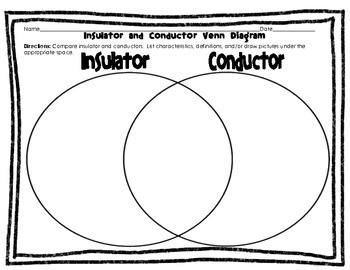
 Conductors and Insulators Venn Diagram
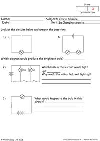
 Electrical Circuit Diagram Worksheet
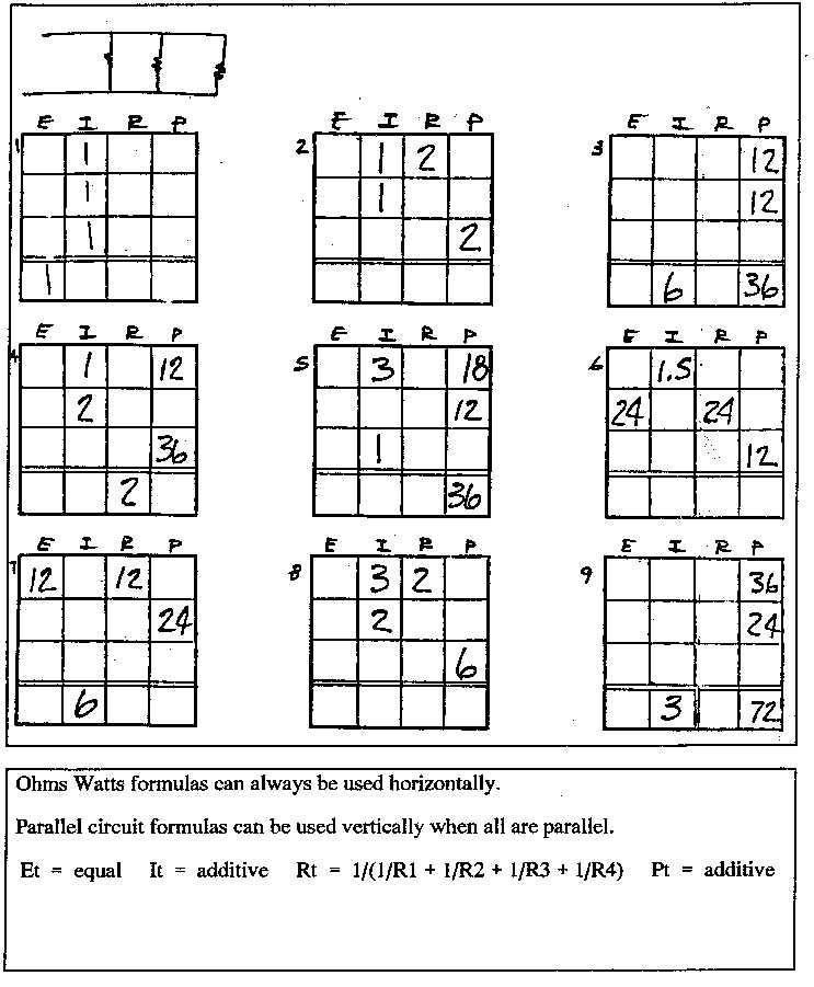
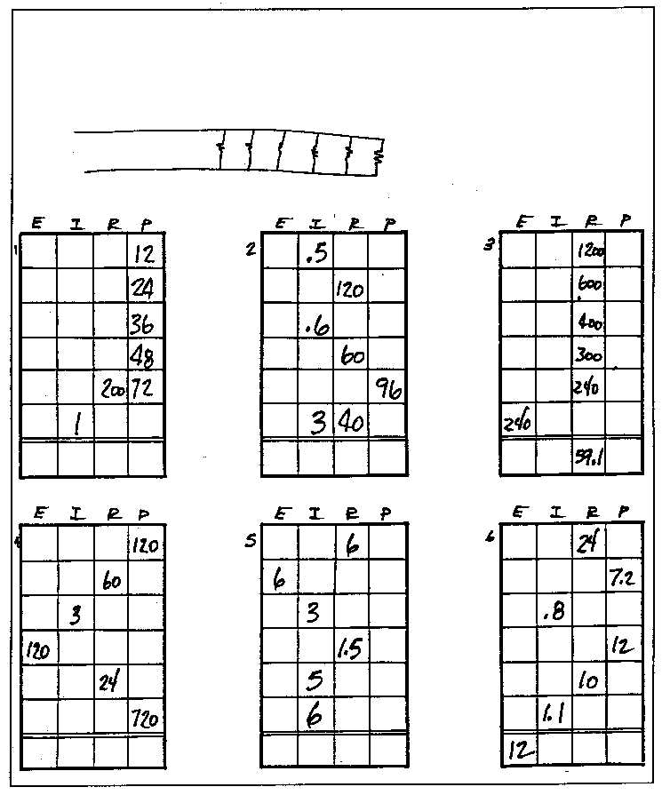
 Parallel Circuit Diagram Worksheet
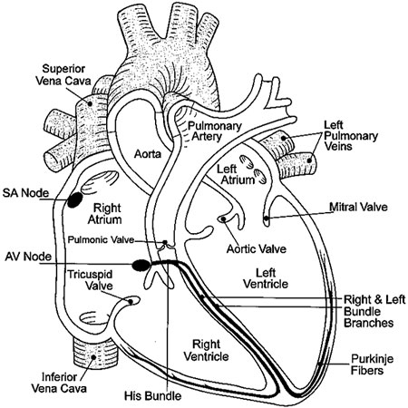
 Heart Diagram Worksheet
 Parallel Circuit Diagram Worksheet
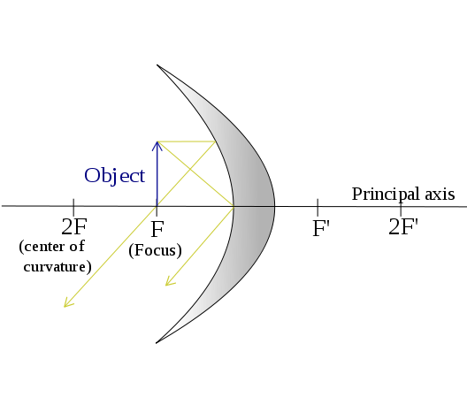
 Concave Mirror Ray Diagram
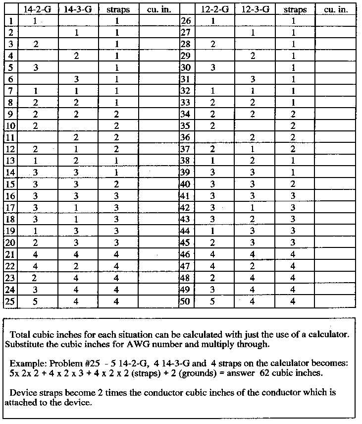
 Junction Box Fill Calculation
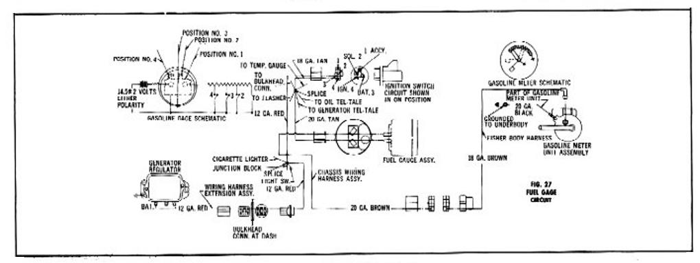
 Car Fuel Gauge Wiring Diagram

 Simple Circuit Schematics
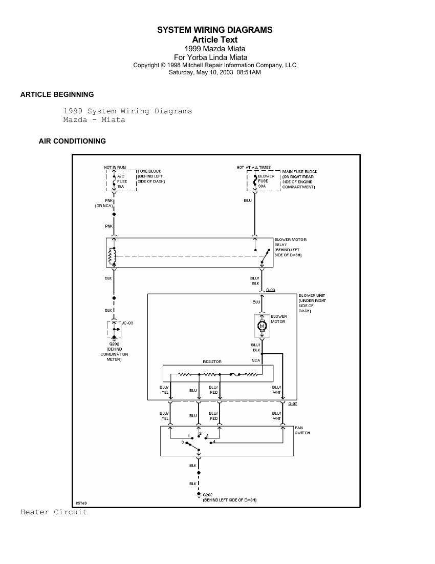
 1999 Mazda Miata Radio Wiring Diagram
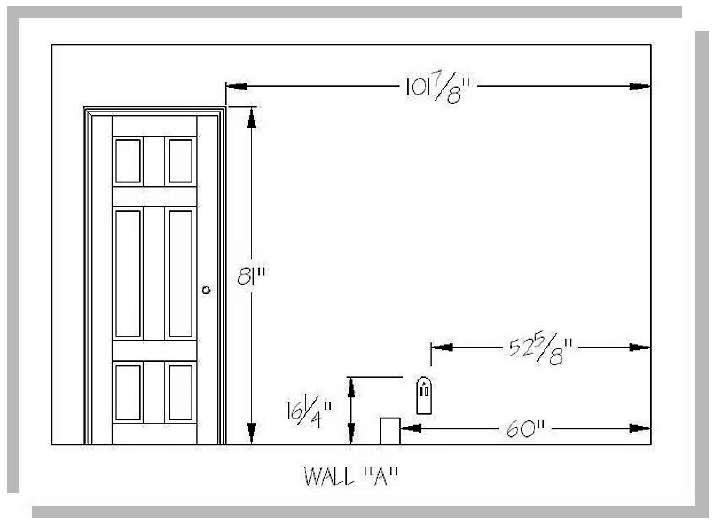
 Kitchen Elevations with Dimensions
 Freightliner Wiring Diagrams

 2009 Subaru Impreza Transmission Diagram
 2009 Subaru Impreza Transmission Diagram
More Other Worksheets
Kindergarten Worksheet My RoomSpanish Verb Worksheets
Cooking Vocabulary Worksheet
DNA Code Worksheet
Meiosis Worksheet Answer Key
Art Handouts and Worksheets
7 Elements of Art Worksheets
All Amendment Worksheet
Symmetry Art Worksheets
Daily Meal Planning Worksheet
What is an electrical diagram?
An electrical diagram is a visual representation that shows the connections and components of an electrical system using symbols and lines to illustrate how the system is wired and how it operates. It helps in understanding the layout of the electrical system and is used for planning, constructing, and troubleshooting electrical circuits and systems.
What are the main components of an electrical diagram?
The main components of an electrical diagram include symbols representing electrical components such as resistors, capacitors, inductors, power sources, and switches; lines and wires indicating electrical connections and paths; labels and numbers for easy identification; and a legend explaining the symbols used in the diagram. These components work together to visually represent the electrical connections and circuitry of a system or device.
What is the purpose of electrical diagrams?
Electrical diagrams serve the purpose of providing a visual representation of an electrical system or circuit, including the connections between various components, the flow of electrical current, and the layout of the system. They are used by engineers, electricians, and technicians to understand, design, troubleshoot, and maintain electrical systems effectively. Electrical diagrams help in identifying faults, planning installations, ensuring safety, and facilitating communication among team members working on the same project.
What are the different types of symbols used in electrical diagrams?
Some of the different types of symbols used in electrical diagrams include power sources (such as batteries and AC power supplies), ground symbols, wires and connections, switches, resistors, capacitors, inductors, transistors, integrated circuits, diodes, transformers, motors, and various other components that are represented by standardized symbols to aid in understanding and designing electrical circuits.
How are electrical diagrams organized?
Electrical diagrams are organized using a standardized system of symbols, lines, and labels to represent different components and connections within a circuit. Typically, diagrams are structured with a clear flow from left to right showing power sources, loads, and the interconnections between them. Additionally, diagrams are often divided into sections or layers to simplify complex circuits and make them easier to understand and troubleshoot.
What is the difference between a one-line diagram and a wiring diagram?
A one-line diagram provides an overview of the electrical system, showing the connections between various components without detailing the physical location or layout of the equipment. On the other hand, a wiring diagram provides a detailed illustration of the physical arrangement of electrical components, showing how they are interconnected with specific wire sizes, colors, and connections.
What are the standard conventions for drawing electrical diagrams?
Standard conventions for drawing electrical diagrams include using specific symbols to represent different components (such as resistors, capacitors, and switches), indicating the direction of current flow with arrows, labelling each component with a unique identifier, and following a clear and logical layout to show the connections and relationships between components accurately. It is also essential to use standard colors for wires (such as black for power lines, red for hot lines, and green for ground lines) to ensure consistency and clarity in the diagram.
How are electrical circuits represented in diagrams?
Electrical circuits are typically represented in diagrams using symbols to denote different components such as resistors, capacitors, inductors, and sources like batteries and generators. Lines connect these components to show how they are interconnected, forming a closed loop that allows the flow of electric current. These diagrams use standard symbols and conventions to provide a visual representation of the circuit's structure and function, helping engineers, technicians, and electricians analyze and troubleshoot the circuit efficiently.
What is the importance of labeling and numbering in electrical diagrams?
Labeling and numbering in electrical diagrams are crucial for clear communication and accurate understanding of the system. Labels and numbers help identify components, connections, and points of reference, making it easier to follow the diagram and troubleshoot any issues that may arise. They also help ensure consistency, efficiency, and safety in electrical installations by providing a standardized way to document and interpret the system's design and functionality.
How can electrical diagrams be used for troubleshooting and maintenance purposes?
Electrical diagrams can be used for troubleshooting and maintenance purposes by providing a visual representation of the electrical system, allowing technicians to locate components, understand the flow of electricity, and identify potential issues such as faulty connections or short circuits. By analyzing the diagram, technicians can trace the paths of electrical circuits, test components for continuity, and pinpoint areas that require repairs or replacements, ultimately streamlining the troubleshooting process and aiding in the efficient maintenance of electrical systems.


Have something to share?
Who is Worksheeto?
At Worksheeto, we are committed to delivering an extensive and varied portfolio of superior quality worksheets, designed to address the educational demands of students, educators, and parents.


Comments