Electric Circuit Worksheets
Electric circuit worksheets are a valuable tool for students to reinforce their understanding of electrical concepts and principles. Designed for both beginners and more advanced learners, these worksheets provide learners with the opportunity to practice applying their knowledge of circuits and components. Whether you are a teacher looking to supplement your lesson plans or a student seeking additional practice, electric circuit worksheets offer a structured and engaging way to enhance your learning experience.
Table of Images 👆
- Series and Parallel Circuits Worksheets
- Circuits and Conductors Worksheet
- Electrical Circuits Worksheets
- Electricity Circuits & Worksheets
- Electrical Circuit Diagram Worksheet
- 3 Phase Forward Reverse Motor Control Circuit
- Start Stop Motor Control Circuit Diagram
- Simple Circuit Diagram Worksheets
- Oscilloscope and Function Generator Circuit
- Parallel Circuit Diagram Worksheet
- Headphone Volume Control Circuit
- Increase Potentiometer Resistor

 Series and Parallel Circuits Worksheets
 Circuits and Conductors Worksheet
 Electrical Circuits Worksheets
 Electricity Circuits & Worksheets
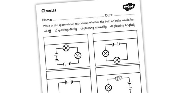
 Electrical Circuit Diagram Worksheet
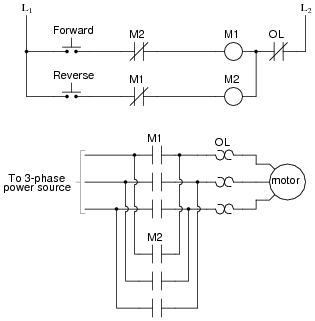
 3 Phase Forward Reverse Motor Control Circuit
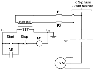
 Start Stop Motor Control Circuit Diagram
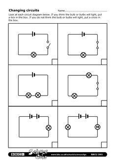
 Simple Circuit Diagram Worksheets
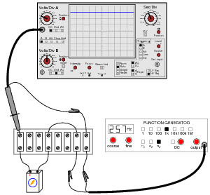
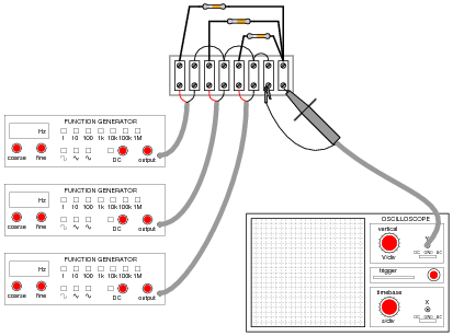
 Oscilloscope and Function Generator Circuit
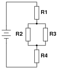
 Parallel Circuit Diagram Worksheet
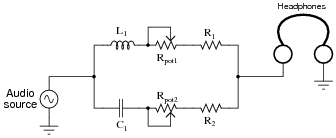
 Headphone Volume Control Circuit
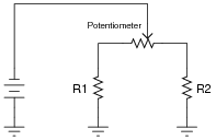
 Increase Potentiometer Resistor
More Other Worksheets
Kindergarten Worksheet My RoomSpanish Verb Worksheets
Cooking Vocabulary Worksheet
DNA Code Worksheet
Meiosis Worksheet Answer Key
Art Handouts and Worksheets
7 Elements of Art Worksheets
All Amendment Worksheet
Symmetry Art Worksheets
Daily Meal Planning Worksheet
What is an electric circuit?
An electric circuit is a path that allows electricity to flow, typically made up of components like conductors, resistors, capacitors, inductors, and power sources. It facilitates the movement of electrons through a closed loop, enabling the transfer of electrical energy and the operation of various electrical devices and systems.
What are the components of a basic electric circuit?
A basic electric circuit consists of a power source (such as a battery), conductive wires to carry the electric current, a load (such as a light bulb or motor) where the electric energy is transformed into another form, and a switch to control the flow of electricity. These components work together to create a closed loop for the electricity to flow through and power the load.
How does a closed circuit differ from an open circuit?
In a closed circuit, there is a complete pathway for the electric current to flow from the power source to the load and back. This allows the electrical energy to power the device or appliance connected to the circuit. In contrast, an open circuit is broken or incomplete, preventing the current from flowing and leading to a lack of power or function in the connected device.
What is the purpose of a switch in an electric circuit?
The purpose of a switch in an electric circuit is to open or close the circuit, allowing or interrupting the flow of electricity. Switches are used to control the flow of current, turning devices on or off, and providing a means to disconnect power to equipment for maintenance or safety purposes.
How does a series circuit differ from a parallel circuit?
In a series circuit, the electrical components are connected in a single path, where the same current flows through each component one after the other. Whereas in a parallel circuit, the components are connected in separate branches, allowing different currents to flow through each component simultaneously. Series circuits have one path for current flow and if one component fails, the entire circuit will be interrupted, while in a parallel circuit, each component has its own path for current flow and failure of one component does not affect the others.
What is the role of a resistor in an electric circuit?
A resistor in an electric circuit regulates the flow of electric current by providing resistance to the flow of electrons. This resistance helps control the amount of current that flows through the circuit, enabling devices to operate at their intended levels and protecting them from damage due to excessive current flow. Additionally, resistors are often used to divide voltage, limit current, and adjust signal levels in various electronic applications.
How does the voltage affect the current in a circuit?
Ohm's Law states that current (I) in a circuit is directly proportional to voltage (V) and inversely proportional to resistance (R), with the formula I = V/R. This means that as the voltage increases in a circuit, the current will also increase, provided that the resistance remains constant. In other words, a higher voltage will lead to a higher current flow through the circuit.
How can you calculate the total resistance in a series circuit?
To calculate the total resistance in a series circuit, you simply add up the individual resistances of each component in the circuit. The formula for calculating total resistance in a series circuit is Rt = R1 + R2 + R3 + ... + Rn, where Rt is the total resistance, and R1, R2, R3, ... Rn are the individual resistances of each component in the circuit.
How can you calculate the total current in a parallel circuit?
To calculate the total current in a parallel circuit, you need to add up the currents flowing through each individual branch of the circuit. This can be done by applying Ohm's Law (I = V/R) to each branch to calculate the current, and then summing up these individual currents to find the total current flowing in the circuit.
What is the potential difference across a component called?
The potential difference across a component is called voltage. It is measured in volts and represents the electrical pressure or difference in electric potential energy between two points in a circuit.


Have something to share?
Who is Worksheeto?
At Worksheeto, we are committed to delivering an extensive and varied portfolio of superior quality worksheets, designed to address the educational demands of students, educators, and parents.


Comments