Circuit Diagrams Worksheet for Students
Circuit diagrams worksheets provide a valuable learning tool for students interested in the world of electrical engineering and physics. These worksheets offer a comprehensive exploration of circuit components, their connections, and the flow of electricity within a circuit. With clear and concise diagrams, students can grasp complex concepts and develop their problem-solving and analytical skills.
Table of Images 👆
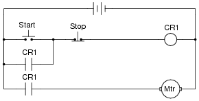
 Ladder Diagram Start Stop Motor Control Starter Switch
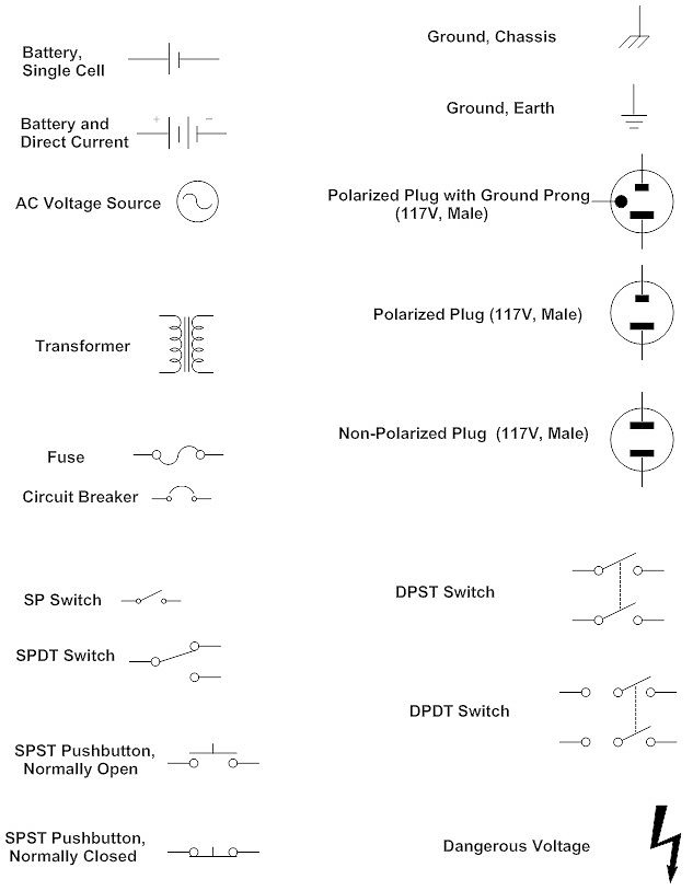
 Wiring Diagram Symbols Automotive

 Motor Control Circuit Ladder Diagram

 Circuit Symbol Clip Art
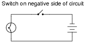
 Alternative Electric Circuit Switch
More Student Worksheets
Middle School Student Goals WorksheetWho I AM Student Worksheet
High School Student Information Worksheet
Student Art Critique Worksheet
Student Getting to Know You Worksheet
Daily Journal Worksheet for Students
Star Student Printable Worksheet
Self-Esteem Worksheets for Students
What is the purpose of a circuit diagram?
A circuit diagram is used to visually represent the components, connections, and functions of an electrical circuit. Its primary purpose is to provide a clear and concise overview of how a circuit is structured and how the components are interconnected, facilitating the design, analysis, and troubleshooting of electrical circuits. It helps engineers, electricians, and technicians to understand and work with complex electrical systems effectively.
Why do circuit diagrams use symbols to represent components?
Circuit diagrams use symbols to represent components because it helps to simplify and standardize the design and understanding of circuits. Using symbols makes it easier to visualize the circuit layout without needing to draw each component realistically, saving time and space. Additionally, symbols help ensure consistency and clarity across different circuit diagrams, making them universally understood by engineers, technicians, and anyone working with electronics.
What does a straight line in a circuit diagram represent?
A straight line in a circuit diagram typically represents a wire that connects two or more components in the circuit, allowing the flow of electric current between them. It is used to show the path of the electrical connection, ensuring that the components are connected properly for the circuit to function as intended.
What does a zigzag line in a circuit diagram represent?
A zigzag line in a circuit diagram represents a resistor, which is a passive two-terminal electrical component that limits or controls the flow of electric current in a circuit. Resistor symbols are often shown as zigzag lines to differentiate them from other components in the circuit diagram.
What is the symbol for a battery in a circuit diagram?
The symbol for a battery in a circuit diagram is a set of parallel lines. The longer line represents the positive terminal, and the shorter line represents the negative terminal.
How is a switch represented in a circuit diagram?
A switch is typically represented in a circuit diagram by using a simple, on/off contact symbol. This symbol consists of a straight line with a gap, which is meant to represent the opening and closing of the switch to control the flow of current in the circuit. The switch symbol is placed in the path of the circuit where the switch would physically be located to indicate its function of controlling the flow of electricity in the circuit.
What is the symbol for a resistor in a circuit diagram?
The symbol for a resistor in a circuit diagram is a zigzag line that represents the resistance component in the electrical circuit.
How is a light bulb represented in a circuit diagram?
A light bulb is typically represented in a circuit diagram as a circle with a cross inside it, symbolizing the filament. It is connected to the power supply through lines that indicate the circuit path, usually with a switch to control the flow of electricity to the bulb.
What does an arrow in a circuit diagram indicate?
An arrow in a circuit diagram indicates the direction of conventional current flow within the circuit. It signifies the path that positive charge carriers would take as they move through the components of the circuit.
How can circuit diagrams be helpful in troubleshooting electrical circuits?
Circuit diagrams can be helpful in troubleshooting electrical circuits by providing a visual representation of the circuit's components and their connections. By referencing the circuit diagram, technicians can easily identify the various elements in the circuit and trace the flow of electricity, allowing them to quickly pinpoint any faults or discrepancies. This visual aid can streamline the troubleshooting process, making it more efficient and effective in locating and resolving any issues within the electrical system.


Have something to share?
Who is Worksheeto?
At Worksheeto, we are committed to delivering an extensive and varied portfolio of superior quality worksheets, designed to address the educational demands of students, educators, and parents.


Comments