Bill Nye Electric Circuit Worksheet
Worksheets play a crucial role in the learning process, providing students with a structured and organized approach to grasp complex concepts. For those eager to enhance their understanding of electric circuits, the Bill Nye Electric Circuit Worksheet serves as an invaluable resource. Designed specifically for students interested in the subject of electricity and circuitry, this worksheet delves into the intricacies of electric circuits, empowering learners to strengthen their knowledge and grasp the fundamentals with ease.
Table of Images 👆

 Bill Nye Static Electricity Worksheet Answers

 Bill Nye Static Electricity Worksheet

 H-Bridge Circuit Diagram
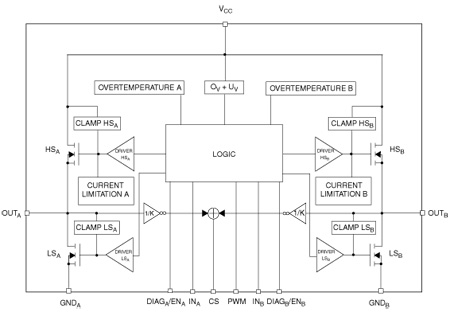
 H-Bridge Circuit Diagram

 H-Bridge Circuit Diagram

 H-Bridge Circuit Diagram

 H-Bridge Circuit Diagram

 H-Bridge Circuit Diagram

 H-Bridge Circuit Diagram

 H-Bridge Circuit Diagram

 H-Bridge Circuit Diagram

 H-Bridge Circuit Diagram

 H-Bridge Circuit Diagram

 H-Bridge Circuit Diagram

 H-Bridge Circuit Diagram

 H-Bridge Circuit Diagram

 H-Bridge Circuit Diagram

 H-Bridge Circuit Diagram

 H-Bridge Circuit Diagram

 H-Bridge Circuit Diagram
More Other Worksheets
Kindergarten Worksheet My RoomSpanish Verb Worksheets
Cooking Vocabulary Worksheet
DNA Code Worksheet
Meiosis Worksheet Answer Key
Art Handouts and Worksheets
7 Elements of Art Worksheets
All Amendment Worksheet
Symmetry Art Worksheets
Daily Meal Planning Worksheet
What is an electric circuit?
An electric circuit is a closed loop through which an electric current flows. It consists of electrical components, such as resistors, capacitors, and inductors, connected by conductive wires. The circuit enables the flow of electric charge from a power source, such as a battery or generator, through the components and back to the source, allowing for the transfer of electrical energy to perform useful tasks, like powering electronic devices.
What are the main components of an electric circuit?
The main components of an electric circuit are a voltage source, such as a battery or power supply, conductive wires to carry the electric current, a load or device that consumes the electrical energy, such as a light bulb or motor, and components like resistors, capacitors, and transistors that control the flow of current or store energy within the circuit. These components work together to provide a pathway for the flow of electricity and to perform specific functions within the circuit.
What is the purpose of a power source in an electric circuit?
The purpose of a power source in an electric circuit is to provide the necessary energy or voltage for the circuit to operate and to supply the electrons needed for current to flow. It creates an electrical potential difference that drives the movement of electrons through the circuit, allowing the electrical components to work and perform their intended functions.
How does current flow in a circuit?
Current flows in a circuit when there is a closed loop or path that allows electrons to move from the negative terminal of the power source (such as a battery) to the positive terminal. As the electrons move through the circuit, they carry electrical energy and create an electrical current. The flow of current is driven by the voltage difference between the two terminals, which causes the electrons to move in a direction from negative to positive.
What is the role of a switch in an electric circuit?
A switch in an electric circuit serves to control the flow of electricity by opening or closing the circuit. When the switch is closed, it allows the current to flow through the circuit, powering the connected electrical device. Conversely, when the switch is open, it interrupts the flow of electricity, turning off the device. Switches are essential components in electrical systems as they provide a way to easily control the operation of various devices and ensure the safety of the circuit.
What is resistance, and how does it affect the flow of current?
Resistance is the opposition of a material to the flow of electric current. It is measured in ohms and is caused by the collisions of electrons with atoms in the conductor. As resistance increases, the flow of current decreases because the electrons have more difficulty moving through the material. This relationship is described by Ohm's Law, which states that current is inversely proportional to resistance, meaning as resistance increases, current decreases, and vice versa.
What are the different types of resistors?
There are several types of resistors used in electronic circuits, including carbon film resistors, metal film resistors, wirewound resistors, ceramic resistors, and variable resistors (such as potentiometers and rheostats). Each type has specific characteristics and is used for different applications based on factors such as precision, power rating, temperature coefficient, and stability.
How does a series circuit differ from a parallel circuit?
A series circuit has only one pathway for current to flow, with the components connected in a line, so if one component fails, the circuit is broken. In contrast, a parallel circuit has multiple pathways for current to flow, with each component connected to the power source independently, allowing for continuous operation even if one component fails.
What is the importance of using proper wiring and safety measures in circuits?
Using proper wiring and safety measures in circuits is crucial to prevent electrical hazards such as short circuits, electrocution, and fires. Proper wiring ensures that the electrical current flows smoothly and safely throughout the circuit, reducing the risk of overheating and electrical failures. Safety measures such as grounding, using circuit breakers, and insulating wires help to protect people and property from potential electrical accidents. Overall, adhering to these practices is essential for maintaining a safe and efficient electrical system in homes, workplaces, and other settings.
How do electrical circuits impact our daily lives?
Electrical circuits impact our daily lives in numerous ways by powering essential devices and systems. They enable us to use electronics such as smartphones, TVs, and computers, power our homes with lighting and heating, and operate appliances like refrigerators and washing machines. Circuits also play a crucial role in transportation systems, communication networks, medical equipment, and infrastructure. Overall, electrical circuits are fundamental in modern society, providing the necessary power for various aspects of our daily routines and activities.


Have something to share?
Who is Worksheeto?
At Worksheeto, we are committed to delivering an extensive and varied portfolio of superior quality worksheets, designed to address the educational demands of students, educators, and parents.


Comments